
Chapter 3 Hydraulics: Gravity Dam Design#
1. Introduction#
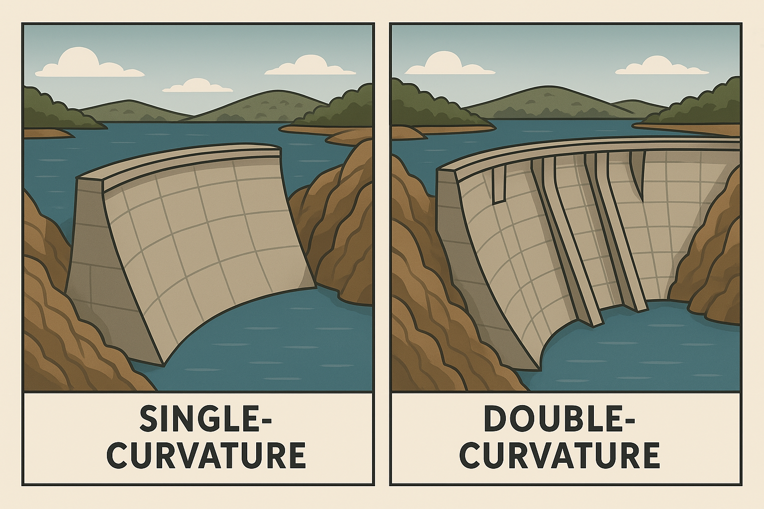
Fig. 12 **Figure 3.12 **: Types of Gravity Dam.#
A dam is a hydraulic structure constructed across a river, stream, or watercourse to store, control, or divert water for various purposes. In water resources engineering, dams play a critical role in:
Water supply for domestic, agricultural, and industrial use
Flood control by regulating downstream flow
Hydropower generation through controlled release of water
Irrigation by maintaining reservoir levels
Navigation by stabilizing river flow
Recreation and ecosystem support
Dams are designed to withstand hydraulic, structural, and environmental loads, and their type and configuration depend on site topography, geology, hydrology, and intended function.
📌 Dam classification#
Dams can be classified based on several criteria
🔹 By Hydraulic Design#
Overflow dams: e.g., concrete dams that allow water to spill over.
Non-overflow dams: e.g., embankment dams that retain water without overtopping.
🔹 By Structural Design#
Gravity Dam - Relies on its own weight to resist water pressure. - Typically made of concrete or masonry. - Suitable for wide valleys with strong foundations. Gravity Dams depend on weight for stability against overturning, sliding, and crushing.
Optimization involves:
Using ¼ to ⅓ of concrete volume to counter uplift.
¾ to ⅔ volume for resisting overturning and shear.
Inclined upstream face can improve stress distribution.
Hollow gravity dams are lighter alternatives with similar design principles.
-Arch Dam- Curved upstream to transfer loads to abutments. - Requires strong, stable rock walls. - Economical in narrow, steep-sided valleys.
Components: - Arch unit: bounded by horizontal planes - Cantilever unit: bounded by vertical radial planes - Extrados: upstream face- Intrados: downstream face
Advantages: - Material-efficient and cheaper - Minor uplift issues due to narrow base - Can be built on moderate foundations
Disadvantages: - Require strong rock abutments - Specialized design and slow construction - Skilled labor and complex formwork needed
Buttress Dam - Consists of a sloping deck supported by buttresses. - Uses less material than gravity dams. - Suitable for moderate foundations and wider valleys. Buttress Dam require less concrete than gravity dams.
Advantages: - Efficient heat dissipation → faster construction - Safer against overturning/sliding due to inclined face- Better stress distribution on foundation - Suitable for weaker foundations
Disadvantages: - Require more reinforcement and skilled labor - Expensive formwork - High stress on slabs/columns → potential deterioration
🔹 By Usage#
Storage dams: Retain water for supply and regulation.
Diversion dams: Redirect flow for irrigation or hydropower.
Detention dams: Temporarily store floodwater.
🔹 By Construction Material#
Concrete or masonry dams
Earth-fill dams
Rock-fill dams
Earth and rock-fill dams
Concrete-faced rock-fill dams (CFRD)
🔹 By Capacity#
Small, Medium, or Large dams
🧭 Site Selection Guidance#
✅ Gravity Dam#
Topography: Wide valley with ample space.
Foundation: Strong rock capable of bearing high loads.
Material Availability: Abundant concrete or masonry.
Hydrology: Suitable for high water pressure and large reservoirs.
✅ Arch Dam#
Topography: Narrow, V-shaped valley with steep rock abutments.
Foundation: Extremely strong and stable rock.
Material Availability: Less concrete needed.
Hydrology: Ideal for deep reservoirs with high head.
✅ Buttress Dam#
Topography: Moderate width valleys with gentle slopes.
Foundation: Fair to good bearing capacity.
Material Availability: Can use reinforced concrete or precast elements.
Hydrology: Suitable for medium head and moderate reservoir size.
🌍 Advantages and Disadvantages of Dams#
✅ Advantages#
Water regulation: Seasonal and spatial control of water distribution
Flood protection: Acts as buffer during heavy rainfall
Drought mitigation: Stores excess water for dry periods
Sediment control: Reduces downstream sedimentation
❌ Disadvantages#
Environmental impact:
Alters local climate and precipitation patterns
Disrupts ecosystems and terrain
Social risks:
Poor design or maintenance can endanger lives and infrastructure
Potential displacement of communities
📊 Comparative Table of Dam Types#
Dam Type |
Structural Principle |
Material Use |
Foundation Requirement |
Topography Suitability |
Advantages |
Limitations |
|---|---|---|---|---|---|---|
Gravity Dam |
Resists water pressure by weight |
High (concrete/masonry) |
Very strong and stable rock |
Wide valleys |
Simple design, durable |
Expensive, heavy structure |
Arch Dam |
Transfers load to abutments via arch |
Low |
Strong abutments and rock walls |
Narrow, steep-sided valleys |
Material-efficient, elegant structure |
Requires precise geology and construction |
Buttress Dam |
Sloping deck supported by buttresses |
Moderate |
Moderate to good foundation |
Broad valleys with moderate slopes |
Economical, less material than gravity |
Complex design, maintenance-intensive |
🧱 Gravity Dams and Dam Overview in the U.S.#
A gravity dam is a solid structure (typically concrete or masonry) that resists water pressure by its own weight.
🔧 Design Philosophy#
Stability through mass and geometry; Requires strong rock foundation
Triangular cross-section; straight or curved plan; Designed for uplift, water pressure, seismic loads
🧠 Modern Design Philosophy#
Sediment Management: Include low-level outlets
Perpetual Use: Design for long-term sustainability
RESCON Model: World Bank framework for sediment economics
✅ Advantages#
- High resistance to overtopping - Long lifespan (>100 years) - Suitable for narrow valleys
❌ Disadvantages#
- High construction cost - Sensitive to uplift pressure - Requires extensive foundation preparation
🏗️ Types of Dams#
Type |
Description |
Example |
|---|---|---|
Gravity Dam |
Resists water by weight |
Hoover Dam |
Arch Dam |
Curved upstream; transfers load to abutments |
Glen Canyon Dam |
Buttress Dam |
Thin slab supported by buttresses |
Coolidge Dam |
Embankment Dam |
Earth or rockfill; relies on mass |
Oroville Dam |
Diversion Dam |
Redirects flow to canals or tunnels |
Granite Reef Dam |
Cofferdam |
Temporary dam for construction |
Bridge foundations |
Hydropower Dam |
Generates electricity |
Grand Coulee Dam |
🏞️ Dam Design and Considerations#
🧭 Factors Influencing Dam Type#
The choice of dam structure depends on several parameters:
Topography:
U-shaped rocky valleys → Concrete dams
V-shaped valleys → Arch dams
Flat plains → Earth-fill dams
Geology & Foundation: Must support dam weight; foundations range from solid rock to clay.
Material Availability
Spillway Design: Size and location are critical.
⚖️ Structural Loads on Gravity Dams#
Primary Loads:
Water pressure
Dam weight
Uplift pressure
Secondary Loads:
Silt pressure
Wave pressure
Ice pressure
Thermal effects
Dam-foundation interaction
Exceptional Loads:
Earthquakes and other rare events
🧪 Material and Foundation Considerations
Concrete properties: Strength, elasticity, thermal and dynamic behavior.
Foundation: Rock-based assumptions, with detailed geotechnical investigations and in-situ testing.
Grouting and joints: Guidelines for contraction joints, galleries, and seepage control.
🌿 Environmental and Ecological Considerations
Impact on fish and wildlife
Reservoir-induced changes to ecosystems
Cultural and recreational values
Site selection based on minimizing ecological disruption
📐 Design Layout and Appurtenances
Spillways, non-overflow sections, freeboard, and drainage galleries.
Temperature control during construction to prevent cracking.
Instrumentation for monitoring dam behavior post-construction.
📊 Safety and Performance
Factors of safety for sliding, cracking, and foundation stability.
Loading combinations: Usual, unusual, and extreme scenarios.
Performance monitoring: Emphasized for long-term dam integrity.
🏞️ Major Dams in the U.S.#
Dam Name |
Type |
Height (ft) |
River |
State |
|---|---|---|---|---|
Oroville Dam |
Embankment |
770 |
Feather River |
California |
Hoover Dam |
Gravity/Arch |
726 |
Colorado River |
NV/AZ |
Grand Coulee Dam |
Gravity |
550 |
Columbia River |
Washington |
Glen Canyon Dam |
Arch |
710 |
Colorado River |
Arizona |
Dworshak Dam |
Gravity |
717 |
Clearwater River |
Idaho |
💥 Notable Dam Failures in the U.S.#
Event |
Year |
Location |
Fatalities |
Cause |
|---|---|---|---|---|
South Fork Dam |
1889 |
Johnstown, PA |
2,209 |
Poor maintenance, heavy rain |
St. Francis Dam |
1928 |
California |
~450 |
Foundation failure |
Teton Dam |
1976 |
Idaho |
11 |
Piping/internal erosion |
Kelly Barnes Dam |
1977 |
Georgia |
39 |
Rainfall, structural issues |
Edenville Dam |
2020 |
Michigan |
0 |
Structural failure, oversight |
🗺️ Dam Distribution in the U.S. [U.S. Army Corps of Engineers, 2025]#
🇺🇸 Dam Trends in the U.S.#
Earthen dams dominate the landscape.
Peak construction occurred in the 1960s, mostly <25 feet in height.
Majority are privately owned.
Category |
Subcategory / Value |
Description / Notes |
|---|---|---|
By State (Top 5) |
Texas – 7,352 |
Highest number of dams |
Kansas – 6,456 |
||
Mississippi – 6,114 |
||
Georgia – 5,455 |
||
Missouri – 5,366 |
||
By Height |
Low: <100 ft |
Majority of dams fall in this category |
Medium: 100–300 ft |
Includes many flood control and irrigation dams |
|
High: >300 ft |
E.g., Oroville, Hoover |
|
By Construction Period |
Pre-1950s |
Masonry and early concrete dams |
1950–1980s |
Peak of large dam construction |
|
Post-2000s |
Focus on rehabilitation and sediment management |
|
By Type |
Embankment – ~80% |
Most common type |
Gravity – ~10% |
Used in narrow valleys with strong foundations |
|
Arch/Buttress – ~5% |
Specialized applications |
|
Others – ~5% |
Includes diversion, cofferdams, etc. |
🧱 Gravity Dam Stability Analysis – Summary Table#
This table summarizes the key checks for gravity dam stability: sliding, overturning, and stress failure, including governing equations and force/moment components.
Stability Check |
Governing Equation / Criterion |
Forces Considered |
Moment Calculation / Notes |
|---|---|---|---|
Sliding |
\(( F_s = \frac{R}{H} \geq \text{Safety Factor} \)) |
- \(( R \)): resisting force (friction + cohesion) |
No moment; force balance along horizontal direction |
\(( R = W \cdot \tan(\phi) + c \cdot A \)) |
- \(( W \)): weight of dam |
Safety factor typically ≥ 1.5 |
|
Overturning |
\(( \frac{M_R}{M_O} \geq \text{Safety Factor} \)) |
- \(( M_R \)): resisting moment (due to dam weight) |
Moments taken about toe of dam |
\(( M_R = W \cdot \frac{b}{2} \)) |
- \(( b \)): base width |
Safety factor typically ≥ 2.0 |
|
\(( M_O = P \cdot \frac{h}{3} \)) |
- \(( P \)): hydrostatic force |
Includes uplift moment if applicable |
|
Stress Failure |
\(( \sigma = \frac{P}{A} \pm \frac{M}{Z} \)) |
- \(( \sigma \)): normal stress |
Check for tensile stress at heel or toe |
\(( Z = \frac{b^2}{6} \)) (for rectangular section) |
- \(( A = b \cdot 1 \)) (unit length) |
Ensure compressive stress < allowable stress |
|
Check: \(( \sigma_{\text{max}} \leq \sigma_{\text{allow}} \)) |
- Include uplift pressure reduction |
No tension allowed at base (gravity dams) |
🧠 Notes#
Uplift Pressure: Reduces effective weight and adds to sliding/overturning forces.
Safety Factors: Typically ≥ 1.5 for sliding, ≥ 2.0 for overturning, and stress within material limits.
Load Combinations: Include dead load, hydrostatic pressure, uplift, silt, ice, and seismic forces.
🧠 Conceptual Insight#
Dams are critical infrastructure for water storage, flood control, hydropower, and ecosystem management.
Understanding dam types, design philosophy, and historical failures helps improve future resilience and safety.
References#
-[United States Bureau of Reclamation, 1976]- Serves as a technical guide for designing concrete gravity dams of all heights (except those under 50 feet, which are addressed in Design of Small Dams). The book emphasizes sound engineering practices, safety, and environmental stewardship. The design principle encompasses 1) stability requirements (against overturning, sliding, and foundation failure), 2) various load types (dead load, hydrostatic, uplift, and silt), and 3) analysis methods (Gravity, trial-load, and finite element method).
-[United States Bureau of Reclamation, 1976]emphasizes empirical design based on historical Bureau practices, focusing on static stability checks and construction detailing. In contrast, [U.S. Army Corps of Engineers, 1995] manual adopts a more analytical and performance-based approach, integrating dynamic analysis, reevaluation of existing dams, and modern computational tools. While both assume rock foundations and cover sliding, overturning, and stress checks, USACE provides deeper guidance on seismic response and uplift modeling.[Novak et al., 2007] provides a comprehensive and engineering-focused treatment of gravity dam design, covering structural stability, uplift pressure, seepage control, and modern safety considerations.
2. Simulation#
Interactive Trapezoidal Gravity Dam Analysis with Drainage Gallery#
This Python script builds an interactive simulation for analyzing the stability of a trapezoidal gravity dam, incorporating various loads and a user-defined drainage gallery location to assess uplift pressure. Powered by ipywidgets and matplotlib, it visually represents geometry, forces, moments, and outputs factor of safety values.
Geometry Inputs#
Dam Height (H): vertical height of the dam (m)Bottom Width: width of dam base at foundation (m)Top Width: width at dam crest (m)Drain Location: horizontal distance from upstream toe (m) — helps reduce uplift pressure beneath dam
Uplift Pressure Adjustment#
Drainage gallery modifies uplift distribution:
From full hydrostatic pressure at upstream toe
To partial pressure at drain
Tapering to tailwater pressure at downstream
This yields:
Modified uplift force
Updated moment due to uplift
Forces Considered#
Force Type |
Direction |
Description |
|---|---|---|
Dam Weight |
Vertical ↓ |
Gravity from dam mass (concrete) |
Hydrostatic Load |
Horizontal → |
Upstream water pressure |
Sediment Load |
Horizontal → |
Pressure from deposited sediments |
Tailwater Load |
Horizontal ← |
Downstream water pressure (resisting) |
Ice & Wave Loads |
Horizontal → |
Surface impacts due to environmental effects |
Uplift Pressure |
Vertical ↑ |
Reduced by drain gallery |
Stability Computations#
Sliding Factor of Safety (FS)
Overturning Factor of Safety (FS)
Toe Stress
Max base pressure estimated for structural integrity.
Visual Dashboard#
Subplot 1: Trapezoidal dam profile with vertical line showing drain position
Subplot 2: Bar chart of external force magnitudes (kN/m)
Subplot 3: Pie chart of overturning moment contributions from each component
Output Summary#
The script prints:
Self-weight of dam - Uplift force (adjusted by drain) - Total horizontal force
FS against sliding and overturning - Max toe stress with a safe/overstressed label
To run the simulation, place this code in a Jupyter notebook cell and use sliders to explore how dam dimensions and drainage position impact structural performance 💧📐🧱.
Gravity Dam Load Equations — Force and Moment Calculations#
This section outlines the governing equations used to compute all external forces and moments in the interactive gravity dam model, including effects of a drainage gallery that reduces uplift pressure.
1. Dam Geometry and Self-Weight#
Trapezoidal Area:
Weight (Force):
Centroid (Moment Arm from Toe):
2. Hydrostatic Water Pressure (Upstream)#
Force:
Moment Arm:
3. Sediment Pressure#
Force:
Moment Arm:
4. Tailwater Pressure (Downstream)#
Assumed Tailwater Height:
Force:
Moment Arm:
5. Wave and Ice Loads#
Wave Force:
Ice Force:
6. Uplift Pressure (Adjusted by Drain Location)#
Let ( d ) be the drainage location (from upstream toe), and ( B ) the base width.
Upstream Pressure at Toe:
Downstream Pressure at Toe:
Zone 1 (0 to d):
Zone 2 (d to B):
Total Uplift Force & Moment:
7. Stability Factors#
Sliding Safety Factor:
Overturning Safety Factor:
Toe Stress Estimate:
import numpy as np
import matplotlib.pyplot as plt
import ipywidgets as widgets
from IPython.display import display

# 🌊 Adjust uplift based on drainage gallery location
def adjusted_uplift(B, H_eff, H_dw, gamma_w, drain_pos):
    h_up = gamma_w * H_eff
    h_dw = gamma_w * H_dw

    # Split base into two regions: upstream to drain, drain to downstream
    P1 = 0.5 * (h_up + h_up * (1 - drain_pos / B)) * drain_pos
    P2 = 0.5 * (h_up * (1 - drain_pos / B) + h_dw) * (B - drain_pos)

    uplift = P1 + P2
    x1 = drain_pos / 2
    x2 = drain_pos + (B - drain_pos) / 2
    moment = P1 * x1 + P2 * x2

    return uplift, moment

# 💻 Interactive dam analysis
def dam_analysis(H, B_bottom, B_top, drain_location):
    # Constants
    gamma_c = 24
    gamma_w = 9.81
    gamma_s = 13
    phi = 35
    cohesion = 0
    wave_pressure = 5
    ice_pressure = 10
    freeboard = 2
    stress_allow = 3000
    H_dw = H / 3

    # Geometry & weight
    A_dam = H * (B_bottom + B_top) / 2
    W_dam = gamma_c * A_dam
    x_W = (B_bottom**2 + 2*B_bottom*B_top + B_top**2) / (3*(B_bottom + B_top))

    # Hydrostatic & external pressures
    H_eff = H - freeboard
    P_upstream = 0.5 * gamma_w * H_eff**2
    x_upstream = H_eff / 3

    P_sediment = 0.5 * gamma_s * H_eff**2
    x_sed = H_eff / 3

    P_tail = 0.5 * gamma_w * H_dw**2
    x_tail = H_dw / 3

    P_wave = wave_pressure * H_eff
    x_wave = H_eff / 2

    P_ice = ice_pressure * H_eff
    x_ice = H_eff / 2

    # 💧 Uplift pressure adjusted by drain
    uplift_force, M_uplift = adjusted_uplift(B_bottom, H_eff, H_dw, gamma_w, drain_location)

    # 🔁 Vertical resisting force
    R_vert = W_dam - uplift_force
    resist_force = R_vert * np.tan(np.radians(phi)) + cohesion * B_bottom

    # 🔁 Horizontal load & moments
    P_horz = P_upstream + P_sediment + P_wave + P_ice - P_tail
    M_resist = W_dam * x_W
    M_overturn = (
        P_upstream * x_upstream + P_sediment * x_sed +
        P_wave * x_wave + P_ice * x_ice - P_tail * x_tail
    )

    FS_sliding = resist_force / P_horz
    FS_overturn = (M_resist - M_uplift) / M_overturn
    stress_avg = R_vert / B_bottom
    stress_max = 2 * R_vert / B_bottom

    # 🧱 Dam geometry plot
    x_left = (B_bottom - B_top) / 2
    x_right = x_left + B_top
    dam_x = [0, x_left, x_right, B_bottom, 0]
    dam_y = [0, H, H, 0, 0]

    plt.figure(figsize=(14, 5))

    # Dam profile
    plt.subplot(1, 3, 1)
    plt.plot(dam_x, dam_y, color='black', linewidth=2)
    plt.fill(dam_x, dam_y, color='lightgray')
    plt.axvline(x=drain_location, color='blue', linestyle='--', label='Drain Location')
    plt.title("Dam Geometry with Drain")
    plt.xlabel("Width (m)")
    plt.ylabel("Height (m)")
    plt.legend()
    plt.grid(True)

    # Forces bar chart
    plt.subplot(1, 3, 2)
    labels = ['Weight', 'Uplift', 'Water', 'Sediment', 'Wave', 'Ice', 'Tailwater']
    forces = [W_dam, -uplift_force, P_upstream, P_sediment, P_wave, P_ice, -P_tail]
    colors = ['gray', 'lightblue', 'blue', 'brown', 'skyblue', 'purple', 'navy']
    plt.bar(labels, forces, color=colors)
    plt.xticks(rotation=45)
    plt.title("External Forces (kN/m)")
    plt.ylabel("Force")

    # Moments pie chart
    plt.subplot(1, 3, 3)
    moment_labels = ['Water', 'Sediment', 'Wave', 'Ice']
    moments = [P_upstream * x_upstream, P_sediment * x_sed,
               P_wave * x_wave, P_ice * x_ice]
    plt.pie(moments, labels=moment_labels, autopct='%1.1f%%', startangle=90,
            colors=['blue', 'brown', 'skyblue', 'purple'])
    plt.title("Overturning Moment Contributions")

    plt.tight_layout()
    plt.show()

    # 📋 Stability summary
    print("📋 Dam Stability Summary")
    print(f"Self-Weight: {W_dam:.2f} kN/m")
    print(f"Uplift Force (adjusted): {uplift_force:.2f} kN/m")
    print(f"Total Horizontal Load: {P_horz:.2f} kN/m")
    print(f"FS (Sliding): {FS_sliding:.2f}")
    print(f"FS (Overturning): {FS_overturn:.2f}")
    print(f"Max Toe Stress: {stress_max:.2f} kN/m² → {'Safe' if stress_max <= stress_allow else 'Overstressed'}")

# 🎛️ Interactive sliders
H_slider = widgets.FloatSlider(value=30, min=10, max=50, step=1, description='Dam Height (m)')
B_bottom_slider = widgets.FloatSlider(value=20, min=10, max=40, step=1, description='Bottom Width (m)')
B_top_slider = widgets.FloatSlider(value=6, min=2, max=20, step=1, description='Top Width (m)')
drain_slider = widgets.FloatSlider(value=10, min=1, max=39, step=0.5, description='Drain Location (m)')

ui = widgets.VBox([H_slider, B_bottom_slider, B_top_slider, drain_slider])
out = widgets.interactive_output(dam_analysis, {
    'H': H_slider,
    'B_bottom': B_bottom_slider,
    'B_top': B_top_slider,
    'drain_location': drain_slider
})

display(ui, out)
Dam Stability Analysis Report#
This report summarizes the stability analysis of a gravity dam using hydrostatic, sediment, wave, and ice pressures. Uplift pressure is adjusted based on the location of a drainage gallery. The dam is evaluated for sliding, overturning, and toe stress safety.
🧱 Geometry & Inputs#
Parameter |
Value |
Units |
|---|---|---|
Dam Height ( H ) |
30.0 |
m |
Bottom Width ( B_{\text{bottom}} ) |
20.0 |
m |
Top Width ( B_{\text{top}} ) |
6.0 |
m |
Drain Location from Upstream |
10.0 |
m |
Concrete Unit Weight ( \gamma_c ) |
24.0 |
kN/m³ |
Water Unit Weight ( \gamma_w ) |
9.81 |
kN/m³ |
Sediment Unit Weight ( \gamma_s ) |
13.0 |
kN/m³ |
Soil Friction Angle ( \phi ) |
35.0 |
degrees |
Cohesion |
0.0 |
kPa |
Wave Pressure |
5.0 |
kN/m² |
Ice Pressure |
10.0 |
kN/m² |
Freeboard |
2.0 |
m |
Allowable Toe Stress |
3000.0 |
kN/m² |
Uplift Pressure Adjustment#
Effective Head: \(( H_{\text{eff}} = H - \text{Freeboard} = 28.0 \, \text{m} \))
Tailwater Depth: \(( H_{\text{dw}} = H / 3 = 10.0 \, \text{m} \))
Drain Location: 10.0 m from upstream face
Adjusted Uplift Force: 1374.0 kN/m
Uplift Moment: 13740.0 kN·m
External Forces#
Force Type |
Magnitude (kN/m) |
|---|---|
Self-Weight |
14400.0 |
Uplift (adjusted) |
-1374.0 |
Upstream Water |
3840.0 |
Sediment |
5100.0 |
Wave |
140.0 |
Ice |
280.0 |
Tailwater |
-480.0 |
Moment Analysis#
Moment Source |
Contribution (kN·m) |
|---|---|
Upstream Water |
1280.0 |
Sediment |
1700.0 |
Wave |
1960.0 |
Ice |
3920.0 |
Tailwater |
-160.0 |
Uplift |
-13740.0 |
Self-Weight |
9600.0 |
Stability Results#
Check |
Value |
Status |
|---|---|---|
FS (Sliding) |
1.42 |
✅ Safe |
FS (Overturning) |
0.85 |
⚠️ Unsafe |
Max Toe Stress |
1374.0 |
✅ Below Limit |
Visualization Summary#
Dam Geometry: Trapezoidal profile with labeled drain location
Force Distribution: Bar chart showing magnitude and direction
Moment Contributions: Pie chart highlighting overturning sources
Interpretation: Uplift and overturning dominate instability; heel extension or drainage optimization recommended
References#
USBR Design Standards for Gravity Dams
FHWA Hydraulic Engineering Circulars
Bowles, J.E. (1996). Foundation Analysis and Design
IS 6512: Criteria for Design of Gravity Dams
💡 Consider increasing heel width, optimizing drain location, or adding shear keys to improve sliding and overturning resistance.
3. Self-Assessment#
Interactive Gravity Dam Stability Analysis — Full Documentation#
This Markdown document provides a complete overview of the interactive trapezoidal gravity dam model, including conceptual understanding, reflection prompts, governing equations, and an engineering quiz to reinforce learning. The model evaluates dam stability under various load conditions and allows users to explore how geometry and drainage location affect performance.
Conceptual Overview#
A gravity dam relies on its mass to resist horizontal forces from water, sediment, and environmental loads. This tool models a trapezoidal dam cross-section and calculates:
Structural weight and moment resistance
Hydrostatic, wave, and ice pressures
Sediment and tailwater loads
Uplift pressure adjusted by user-defined drain location
Safety factors against sliding, overturning, and toe stress are evaluated using engineering equilibrium principles.#
###Reflective Questions
💭 How does changing the base width influence dam safety?
💭 Why is the location of drainage galleries important for managing uplift?
💭 What environmental factors contribute to non-hydrostatic forces on a dam?
💭 How do tailwater conditions help resist overturning?
💭 What trade-offs exist between material cost and dam safety?
Governing Equations#
Geometry and Weight#
Area: \(( A_{\text{dam}} = H \cdot \frac{B_{\text{bottom}} + B_{\text{top}}}{2} \))
Weight: \(( W = \gamma_c \cdot A_{\text{dam}} \))
Centroid:
\(( x_W = \frac{B_{\text{bottom}}^2 + 2B_{\text{bottom}}B_{\text{top}} + B_{\text{top}}^2}{3(B_{\text{bottom}} + B_{\text{top}})} \))
Horizontal Loads#
Upstream Pressure:
\(( P_{\text{upstream}} = \frac{1}{2} \cdot \gamma_w \cdot H_{\text{eff}}^2 \))
\(( x_{\text{upstream}} = \frac{H_{\text{eff}}}{3} \))Sediment Pressure:
\(( P_{\text{sediment}} = \frac{1}{2} \cdot \gamma_s \cdot H_{\text{eff}}^2 \))
\(( x_{\text{sediment}} = \frac{H_{\text{eff}}}{3} \))Wave Load:
\(( P_{\text{wave}} = P_w \cdot H_{\text{eff}} \))
\(( x_{\text{wave}} = \frac{H_{\text{eff}}}{2} \))Ice Load:
\(( P_{\text{ice}} = P_i \cdot H_{\text{eff}} \))
\(( x_{\text{ice}} = \frac{H_{\text{eff}}}{2} \))Tailwater Resistance:
\(( P_{\text{tail}} = \frac{1}{2} \cdot \gamma_w \cdot \left(\frac{H}{3}\right)^2 \))
\(( x_{\text{tail}} = \frac{H/3}{3} \))
Uplift Force (Drain-Adjusted)#
Let ( d ) be drain location from upstream toe and ( B ) the base width:
Zone 1:
\(( P_1 = \frac{1}{2} \cdot \left(h_{\text{up}} + h_{\text{up}} \cdot \left(1 - \frac{d}{B}\right)\right) \cdot d \))
\(( x_1 = \frac{d}{2} \))Zone 2:
\(( P_2 = \frac{1}{2} \cdot \left(h_{\text{up}} \cdot \left(1 - \frac{d}{B}\right) + h_{\text{dw}}\right) \cdot (B - d) \))
\(( x_2 = d + \frac{B - d}{2} \))Uplift Force: \(( P_{\text{uplift}} = P_1 + P_2 \))
Uplift Moment: \(( M_{\text{uplift}} = P_1 \cdot x_1 + P_2 \cdot x_2 \))
Stability Analysis#
Sliding Safety Factor:
\(( FS_{\text{sliding}} = \frac{R_{\text{vert}} \cdot \tan(\phi) + c \cdot B}{P_{\text{horizontal}}} \))Overturning Safety Factor:
\(( FS_{\text{overturning}} = \frac{M_{\text{resist}} - M_{\text{uplift}}}{M_{\text{overturning}}} \))Toe Stress:
\(( \text{Stress}_{\text{max}} = \frac{2 \cdot R_{\text{vert}}}{B} \))
✅ Quiz#
1. What is the primary purpose of a drainage gallery in a gravity dam?#
To increase dam weight
To reduce uplift pressure
To store water for irrigation
To prevent sediment deposition
2. Which equation calculates hydrostatic pressure on the dam’s upstream face?#
\(( P_{\text{upstream}} = \frac{1}{2} \cdot \gamma_w \cdot H^2 \))
\(( P = \gamma_w \cdot H \))
\(( P = \gamma_c \cdot A_{\text{dam}} \))
\(( P = \frac{1}{2} \cdot \gamma_s \cdot H^2 \))
3. What is the formula for sliding factor of safety?#
\(( FS = \frac{R_{\text{vert}} \cdot \tan(\phi) + c \cdot B}{P_{\text{horizontal}}} \))
\(( FS = \frac{M_{\text{resist}}}{M_{\text{overturn}}} \))
\(( FS = \frac{P_{\text{upstream}}}{P_{\text{tail}}} \))
\(( FS = \frac{R_{\text{vert}}}{B} \))
4. How does increasing base width affect dam stability?#
Decreases sliding FS
Increases overturning FS
Increases uplift pressure
Decreases dam’s weight
5. Why is the centroid location important?#
Determines maximum stress
Used to calculate resisting moment
Indicates uplift peak
Determines dam height
This interactive model links geometry, physics, and design intuition into a full dam engineering dashboard. Adjust, reflect, and learn from every angle 💧📐🧱.